
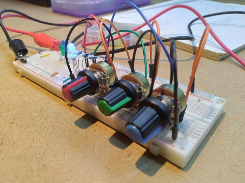
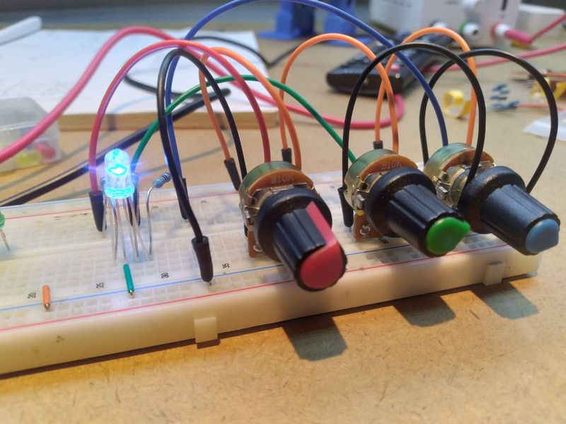
An RGB LED has four outputs: three LEDs (red blue and green), as well as either a common cathode (-) or a common anode (+). The RGB LED referred to in this post is a common cathode. By scaling the voltage of each of the LEDs within, the RGB LED is able to produce different colors of visible light. The post will contain two examples. In the first example, the color of the RGB will be controlled via an analog input, whereas in the second example, the input will be given digitally.

Analog Controller
Digital PWM

Rainbow Example
Pulse-width modulation is used to control the output of the LED on a digital level. The program below uses it to display the colors of the rainbow at an interval of 0.8 seconds.
The code begins by defining the constant values of RED_PIN, BLUE_PIN, and GREEN_PIN. In the void setup, they are later declared as outputs.
#define RED_PIN 5
#define BLUE_PIN 4
#define GREEN_PIN 3

void setup() {
  // initialize digital pin LED_BUILTIN as an output.
  pinMode(RED_PIN, OUTPUT);
  pinMode(BLUE_PIN, OUTPUT);
  pinMode(GREEN_PIN, OUTPUT);
}

void loop() {
  analogWrite(RED_PIN, 255); // red
  analogWrite(GREEN_PIN, 8);
  analogWrite(BLUE_PIN, 0);
  delay(800);
  analogWrite(RED_PIN, 255); // orange
  analogWrite(GREEN_PIN, 162);
  analogWrite(BLUE_PIN, 0);
  delay(800);
  analogWrite(RED_PIN, 255); // yellow
  analogWrite(GREEN_PIN, 242);
  analogWrite(BLUE_PIN, 0);
  delay(800);
  analogWrite(RED_PIN, 47); // green
  analogWrite(GREEN_PIN, 255);
  analogWrite(BLUE_PIN, 0);
  delay(800);
  analogWrite(RED_PIN, 0); // sky blue
  analogWrite(GREEN_PIN, 255);
  analogWrite(BLUE_PIN, 255);
  delay(800);
  analogWrite(RED_PIN, 0); // blue
  analogWrite(GREEN_PIN, 21);
  analogWrite(BLUE_PIN, 255);
  delay(800);
  analogWrite(RED_PIN, 255); // violet
  analogWrite(GREEN_PIN, 0);
  analogWrite(BLUE_PIN, 255);
  delay(800);
  }