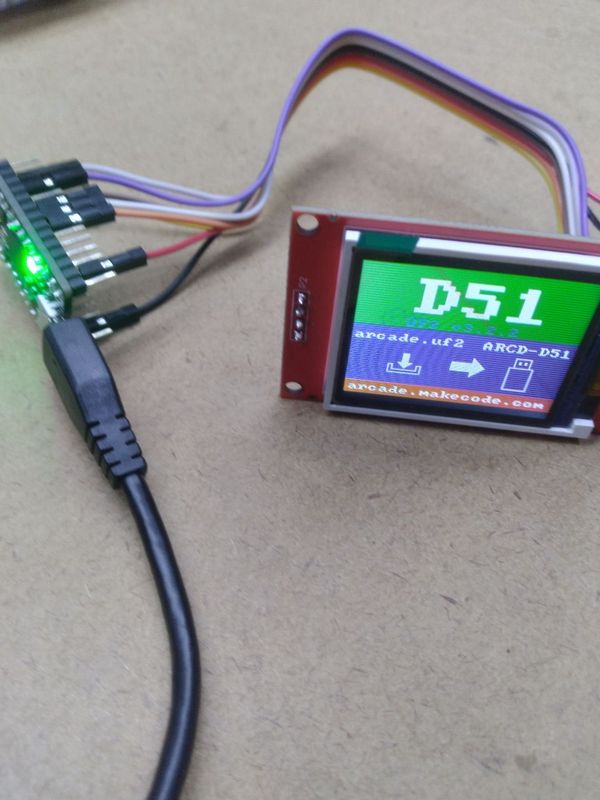
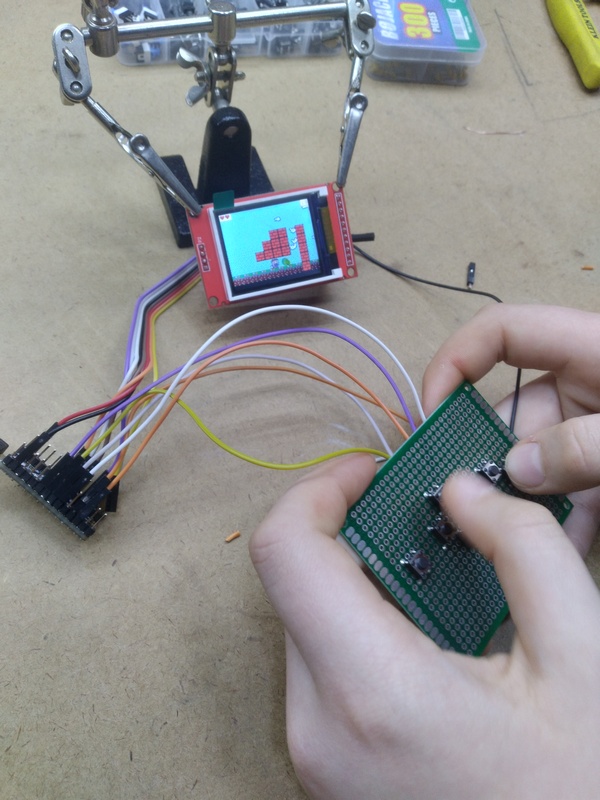
As someone who has been fascinated with with video-game design for a long time now, I’ve decided to dig even deeper and create my own mini console. Lucky for me, I wasn’t the first person to do this, so I didn’t have to stumble in the dark. Instead, I used a tutorial made by Adafruit, which utilized their custom ItsyBitsy M4 board. Since the board is now connected to the display, I’m able to create and upload games using the MakeCode Arcade code editor, which offers block coding as well as JavaScript and Python. For now, I’ve connected the ItsyBitsy to a display and a few buttons for interacting with the game.
https://learn.adafruit.com/makecode-arcade-with-samd51-m4
Materials
- ItsyBitsy M4 Express Board
- DSD TECH 1.8 Inch TFT LCD Display
- x7 push-buttons
- wires
- prototyping board
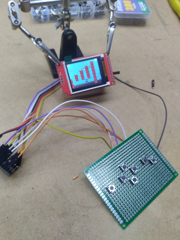
Connecting the Display
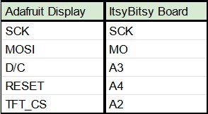
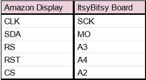
One major issue that I had during this project was connecting the display to the the ItsyBitsy board. While this seems simple at first (just follow the schematic on the tutorial!), its isn’t. The problem was that I was planning to use a different display to connect to the board, and not one that was sold by Adafruit. To my surprise, this complicated things, as the names of the inputs and outputs on the display were different from ones on the display that I was going to use. This didn’t stop me, since I knew the two displays were too similar to have completely different outputs. After some research, I learned that the names of the inputs and outputs created by hardware companies aren’t the same if the same product is made by another company. Below is a side by side comparison of the input and output list provided in the tutorial, and the one I ended up using.
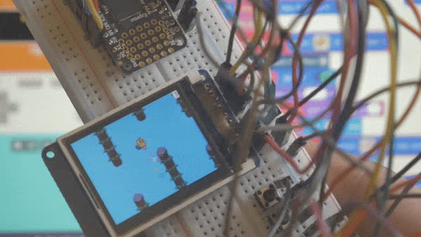
Gallery